My first exposure to CAD modeling software was in 2015 to Autodesk Inventor, soon followed by SolidWorks, Autodesk Fusion, and CATIA. Experience in each program makes me more capable and effective in all. Along with modeling software, I have experience in FEA simulation for structural parts using Solidworks Simulation tools, fluid flow and thermal management using FloEFD combined with CATIA, and CAD data management in Windchill PLM software.
Content List
Techniques
Surface Modeling
Organic forms and curved shapes require use of surface modeling. Surfaces are bodies with no volume, defined from cross sections, paths, and other supporting geometry. Some applications of surfaces are trimming stock volumes into desired shapes and defining boundaries of a volume to be considered as a solid.

Credit to Autodesk
Fusion Surface Modeling
Fusion has some limited surface modeling tools, suitable for simple tasks that stick to planar sketches.


Rhino3D Surface Modeling
For the complex surfacing used in aircraft, shipbuilding, and car bodies, dedicated surfacing software like Rhino3D offers greater control and more tools. I’ve started learning how to leverage its power to produce some parts of intermediate complexity.


Importing Custom Geometry
I use surfaces extracted from imported geometry to interface with real hardware.


I use image processing to derive part boundaries from images for custom solutions.


Animations
I create visuals to communicate the essence of parts/assemblies in an intuitive way.


Master/Skeleton Method
Wherever two parts contact one another, there is information shared by both parts. This means when one part needs to change, it will affect parts in contact with it. The images below show how the parts of a common door hinge share properties.


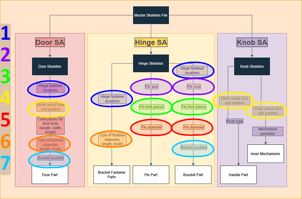
For the example above, the door body contacts both the hinges and the knob, so information about the knob (in yellow) and about the hinges (in blue) need to be accessible by each pair of parts. If the size of the knob changes then the hole in the door must change to match; if the fasteners attaching the hinges to the door change from M4 to M6 then the holes in the door must be enlarged. Within the hinge sub-assembly itself, the brackets and pin are in contact for their entire length; it is convenient to define both parts’ size from the same diameter and set of limit planes.
To design an assembly like this, I would create CAD elements as shown in the colored portions of the hand drawn sketches above to define shared construction features between parts, then structure the part files like the diagram below. Storing common content (circled items) in the Master Skeleton File allows all parts remain synchronized, reducing how often the content must be defined from sixteen times (individual instances of circled diagram content) to to seven (number of circle colors/distinctly different geometry pieces to be shared).
Software
Solidworks

SolidWorks is the industry standard for CAD software, offering strong design and simulation capabilities in a fairly approachable interface. I first used it at the University of Delaware from 2019 to 2022, after which I have utilized a Maker license on my personal machine. SolidWorks is the CAD package I have used the longest overall.
Over the course of my time using SolidWorks, I have done the following:
Drawings:
- Created part drawings of a single component
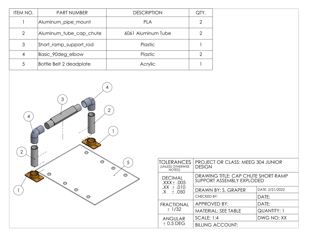
- Created assembly drawings (standard and exploded)
- Created bills of materials
- Customized view settings, such as scale, visual appearance, and layout
- Created title blocks with associative links to source parts
Parts:
- Creation of construction geometry (planes, axis systems, lines, points, etc.) to support features
- Validated motion studies within a sketch
- Performed motion studies using the Motion Study add-in
- Imported external models of stock components for use in designs
- Produced models based on photographs to identical scale
- Used 3D sketches to produce designs containing minimal planar symmetry
- Exported parts in additive manufacturing formats (.stl, .3mf)
- Utilized links to parameters and equations to drive models from an external spreadsheet
- Use of surfaces to modify and produce solid volumes
- Created and used the “block” feature to make common sketch geometry consistent and accessible later
- Used hole wizard to ensure compatibility with standardized hardware
Assemblies:
- Created assemblies with 30+ parts and many mates
- Use of simple mates (coincident, concentric, distance, angle, tangent, etc.)
- Use of advanced mates (width, linear, symmetry, etc.)
- Use of mechanical mates (cam-follower, slot, hinge, gear, etc.)
- Created animated explodes and assemblies for use in presentations
Simulation:
- Set up simulations (boundary conditions, loading method(s), material, etc.)
- Produced reports with relevant results (stress, deformation, displacement, factor of safety, etc.)
Drawings



Parts and Sketches


Assembly


Simulation


Fusion

Autodesk Fusion (formerly Fusion 360) is a CAD solution that focuses heavily on cloud integration, streamlining work between multiple users, and project organization. I first used Fusion following graduation from the University of Delaware in 2022, due to the expiration of my student access to Solidworks and Fusion’s non-commercial free use license. Fusion is the CAD software I have the most experience with for personal use.
Over the course of my time using Fusion, I have done the following:
Parts:
- Creation of construction geometry (planes, axis systems, lines, points, etc.) to support features
- Imported external models of stock components for use in designs
- Produced models based on photographs to identical scale
- Exported parts in additive manufacturing formats (.stl, .3mf)
- Surface modeling, use of surfaces to modify or produce solid volumes
- Worked with imported meshes for solid and surface modeling
- Imported custom svg paths for complicated profiles
- Imported and constrained external components
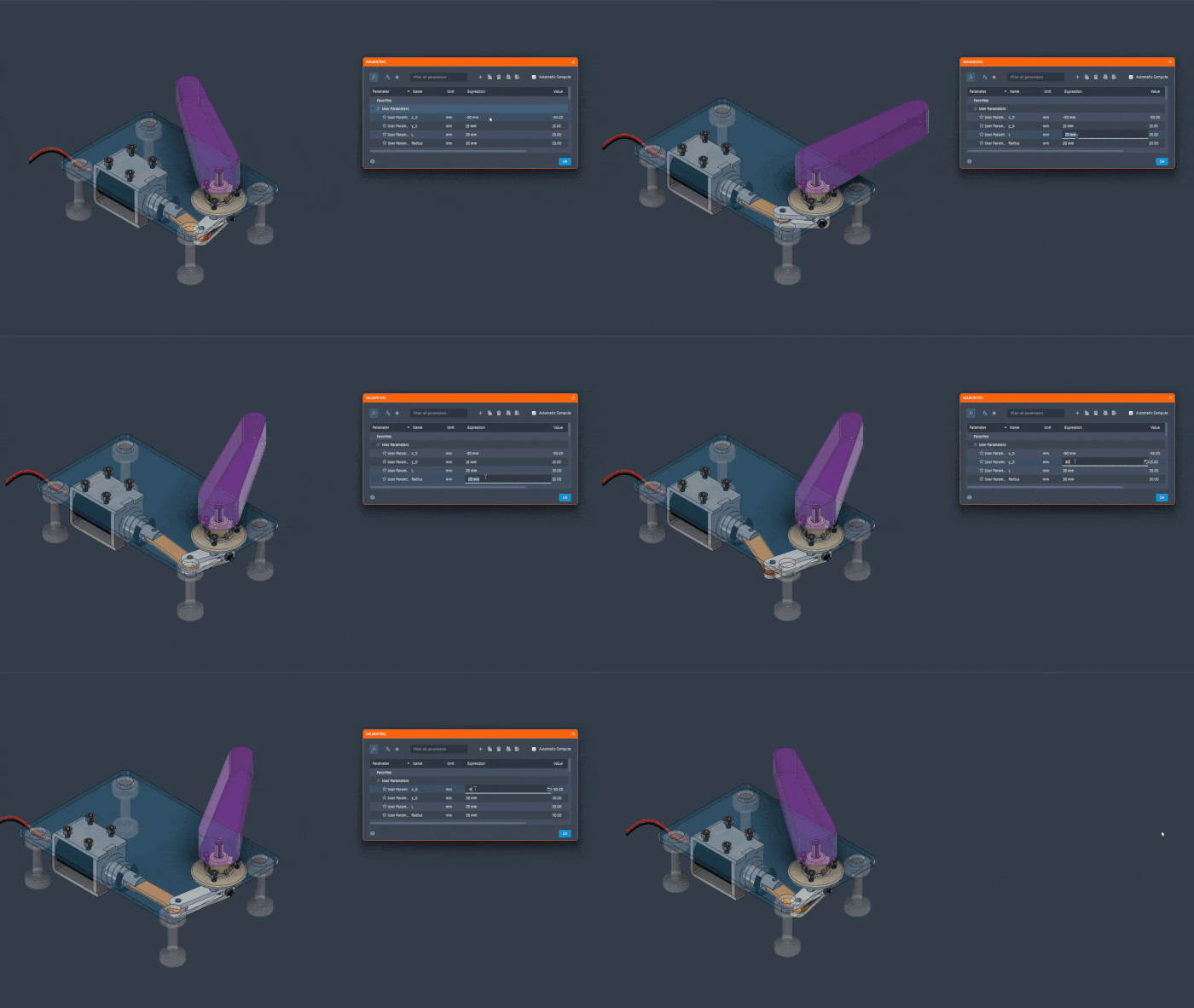
- Robust parametric models that update using formulas and geometric constraints
Assemblies:
- Created assemblies with >10 parts and mates
- Use of simple mates (coincident, concentric, distance, angle, tangent, etc.)
- Performed fit checks between connecting parts
Simulation:
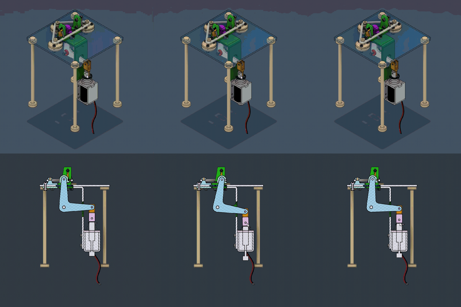
- Performed motion studies by connecting components with joints
- Scripted component behavior to follow analytic formulas
Animation:
- Scripted part motions and transparencies to imitate assembly process
- Manipulated camera angle to show defining views of a part
Fusion is the program used in my Pinball project!


Boolean Operations


CATIA

CATIA (Computer-Aided Three-dimensional Interactive Application) is an extremely powerful CAD package providing designers advanced surface modeling options, sophisticated linking of content within and between model files, efficient assembly management, and many simulation tools. Its high cost restricts its use to aerospace, automotive, and the largest consumer goods companies. I first used CATIA at Stanley Black and Decker in 2023, achieving basic proficiency within 4-6 months and advanced understanding by the end of my first year. CATIA is the CAD software I have the most experience with for professional use.
To maintain compliance with the policies of companies which I have produced CATIA content for, I am unable to directly share any original work here. As an alternative, below are some broader descriptions of my experience with CATIA:
My CATIA Design Approach
- Leveraging master/skeleton modeling techniques to optimize data reuse, streamline links and keep several parts synchronized. This has become my non-negotiable for any assembly containing three or more parts.
- One parent file (skeleton) containing only 1D and 2D geometry (points, lines, curves, sketches, planes, surfaces, etc.) that define crucial geometry and intersections between parts. Essentially, all design decisions are made here.
- Each component is a child of the parent, linking to the content relevant to just that component’s design. Each component is just a permutation of elements derived from the skeleton, to be toggled on or off.
- Thorough use of construction geometry to create support features accessible by all features. I attempt to never create sketches directly on solid faces if possible, instead defining a plane as the solid extrude limit and sketching on the plane. This ensures sketches are never orphaned from their supports.
- Boolean-based modeling where features are compartmentalized into small pieces with limited scope. This prevents cascades of errors and creates a modular design where one iteration of a feature can easily be replaced by another. CATIA facilitates this very well, with solid bodies being the basic building block serving as containers of features, rather than strictly an output of positive operations (pad, revolve, sweep, etc).
- Performing operations as early in the design tree as possible to minimize dependencies; ex. create a fillet as soon as its parent edge exists, rather than after the creation of potential conflicting features.
Modeling Skills I Developed in CATIA
- Cavity-core modeling techniques, which actually model the cavity-electrode and core of the mold, producing the part as the negative space between the two. This guarantees no mechanical conflicts in the injection molding process to product the part.
- Familiarity with injection molding best practices
- Modeling of wire harnesses and connectors, including wires in both routed and stock states to ensure ample space and compliance with minimum bend radii
- Fundamental understanding of industrial design principles that contribute to a product’s sense of identity and value
- Bent sheet metal design using stock material thicknesses and industry-proven principles on feature layout
- Driving sketches, which consolidate relevant geometry together and allow for changes to enacted from one source
- Orderly linking, creating robust models that won’t break due to changes in context
- Use of formulas to parameterize models wherever possible, accelerating iteration speed
My Output From Using CATIA
Parts:
- Created part drawings of precision components up to 0.001 mm
- Applied surface finish callouts to shafts
- Utilized GD&T (Geometric Dimensioning and Tolerancing) with feature control frames to quantify tolerances for holes, profiles, etc.
Parts:
- Created parts for many different purposes:
- Electrical (strain relief grommets, terminal boxes, cable routing features, custom PCB mounts)
- Mechanical (motor housings, interface plates, mounting brackets, motor shafts)
- Airflow (baffles, fans, venting)
- Testing (angle dials, tool fixtures, jigs)
- Verified part design using draft analysis and other tools
- Extensive use of construction geometry (planes, axis systems, lines, points, etc.) to support features
- Created reference models of existing industry products from technical documents
- Imported external models of stock components for use in designs
- Exported parts in additive manufacturing formats (.stl, .3mf)
- Utilized links to parameters and equations to drive models
- Surface modeling, use of surfaces to modify or produce solid volumes
Assemblies:
- Created assemblies with 100+ parts and many mates
- Organize top-level assemblies into sets of logical sub-assemblies, grouping parts that share a purpose (fasteners, interface elements, etc.) or which will be assembled together beforehand
- Verified assembly design using clash checks to identify incorrect fits between parts
- Widespread use of coincident mates between components to remove all degrees of freedom and precisely locate parts
Simulation:
- Created simulation test plans outlining design changes to be examined
- Set up mechanical, thermal, and CFD airflow studies (boundary conditions, control volumes loading method(s)/speeds, material, etc.)
- Produced reports with relevant results (isosurfaces, particle studies, flow diagrams, cross section views of velocity/pressure/temperature, mechanical stress, deformation, displacement, factor of safety, etc.)
- Synthesized results into actionable changes and quantified improvements in performance
Inventor

Autodesk Inventor is the first CAD package I ever used back in 2015, and I credit my early exposure to it (along with 3D printing) as the reason I am a mechanical engineer today. I used it to learn about drafting, basic solid modeling, CAM programming, and surface sculpting. Inventor is the CAD software I rarely use, simply due to narrow adoption.
Over the course of my time using Inventor, I have done the following:
Drawings:
- Created part drawings of a single component
- Created assembly drawings (standard and exploded)
- Created bills of materials
- Customized view settings, such as scale, visual appearance, and layout
Parts:
- Basic solid modeling
- Creation of construction geometry (planes, axis systems, lines, points, etc.) to support features
- Exported parts in additive manufacturing formats (.stl, .3mf)
Assemblies:
- Created assemblies with ~10 parts and moderate amount of mates
- Use of simple mates (coincident, concentric, distance, angle, tangent, etc.)
- Use of advanced mates (width, linear, symmetry, etc.)
- Use of mechanical mates (cam-follower, slot, hinge, gear, etc.)
Simulation:
- Programmed CNC mill paths to produce model geometry based on mill size, type, etc.


